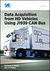
 HEM Data is pleased to announce that it has written a book entitled Data Acquisition from HD Vehicles Using J1939 CAN Bus. It is published by SAE and available from SAE and directly from HEM Data.
This book compares various diagnostic approaches including OBD-II, HD-OBD and World Wide Harmonized (WWH) OBD. In-vehicle network data is valuable for improved maintenance, vehicle and its subsystems performance, fleet management, warranty and legal issues, reliability, durability, and accident reconstruction. Applications discussed include calculating fuel economy, duty cycle analysis, and capturing intermittent faults.
The focus of the book is how to acquire and correctly interpret data from the in-vehicle network of heavy-duty (HD) vehicles using the SAE J1939 standard. The book presents an introduction to CAN, the building block of J1939, and guides the reader through various SAE J1939 standards.
The reader will learn how to determine the available parameters on HD vehicles including their accuracy and sample rates, and how to acquire and convert messages to scaled engineering parameters. Data Acquisition from HD Vehicles Using J1939 CAN Bus is a must-have reference for those interested in getting started with SAE J1939 as well as those who want more detail on how to use it effectively.
Order now by phone (248) 559-5607 or (800) 436-4330.
The book price is $89.95 and with shipping from HEM Data it is $99.00 in the U.S. For worldwide purchases, we recommend buying the e-book directly from SAE.
Table of Contents
Chapter 1 Benefits and Applications of the In-Vehicle Network for
Data Acquisition
1.1 Overview—Data Goldmine
1.2 Focus and Assumptions of This Book
1.3 Access to the Data
1.4 Normal and Requested Messages
1.4.1 Normal Messages
1.4.2 Requested (Diagnostic/Polled/Event) Messages
1.4.3 Requested Versus Normal Messages
1.5 Comparing Light- and Heavy-Duty Vehicle Designs
1.6 Medium-Duty Vehicles
1.7 Applications
1.8 How to Use This Book
References
Chapter 2 Comparison with Traditional Data Acquisition
2.1 Acquiring Data with Our Own Sensors
2.2 In-Vehicle Network Data
2.3 Acquiring Parameters from the Network
2.4 Complications of Network Versus Direct Sensors
Chapter 3 Binary, Hex, Bits, and Bytes
3.1 Introduction to Bits, Binary, and Hexadecimal Conventions
3.2 Hexadecimal Designations
3.3 Introduction to Bits and Bytes
3.4 11- and 29-Bit CAN IDs
3.5 Data Conventions
3.5.1 Conversion Format
3.5.2 Byte Format
3.5.3 Byte Order
Chapter 4 Controller Area Network (CAN) Protocol
4.1 What is CAN?
4.2 What Does CAN Define?
4.2.1 Layer 1—Physical Layer
4.2.2 Level 2—Data Link Layer
4.3 Applications of CAN
4.4 CAN on Light-duty Vehicles Using ISO 15765
References
Chapter 5 J1939 Standard Overview
5.1 Introduction
5.2 Previous In-Vehicle Network Standards (J1708 and J1587)
5.3 J1939 Overview and Industry-Specific Standards
5.3.1 J1939 – Top-Level Document
5.3.2 J1939DA – Digital Annex
5.3.3 J1939/01 – On-Highway Equipment Control and Communication
Network
5.3.4 J1939/02 – Agricultural and Forestry Off-Road Machinery Control and Communication Network
5.3.5 J1939/05 Marine Stern Drive and Inboard Spark-Ignition Engine On-
Board Diagnostics Implementation Guide
5.4 J1939/7x – Background Application Standards
5.4.1 J1939/74 – Application Configurable Messaging
5.4.2 J1939/75 – Generator Sets and Industrial
5.5 J1939/8x
5.5.1 J1939/81 – Network Management
5.5.2 J1939/82 – Compliance—Truck and Bus
5.6 Most Important J1939 Standards
References
Chapter 6 J1939 Lower Layer Specifications
6.1 Physical Layer
6.1.1 J1939/11—Physical Layer—250 kbits/s, Shielded Twisted Pair
6.1.2 J1939/13—Off-Board Diagnostic Connector
6.1.3 J1939/14—Physical Layer, 500 kbits/s
6.1.4 J1939/15—Physical Layer, 250 kbits/s, Unshielded Twisted Pair
6.2 Data Layer
6.2.1 J1939/21—Data Link Layer—Message Format
6.2.2 J1939/21—Data Link Layer—Transmitting Messages>
6.2.2.1 Broadcast Announce Message (Global)
6.2.2.2 Broadcast Long Message Example: PGN-FEE3 (65251)—Engine
Configuration
6.2.2.3 Connection Management (Targeted)
6.2.2.4 Request Messages
6.3 Network Layer (J1939/31)
References
Chapter 7 Application Layer (J1939/71)
7.1 PGNs and SPNs
7.2 J1939 Message Data Format
7.3 Scaling Information
7.4 Transmission Rate
7.5 Digital Annex (J1939DA)
7.6 Logging J1939 Data with a Test Tool
7.6.1 Example J1939/71 Database Editor
7.6.2 Selecting Parameters to Acquire
7.6.3 Finding Available Parameters
7.6.4 Sorting by Name, Unit, or PGN
7.6.5 Defining the Acquisition Rate and Source Address
7.6.6 Importing Proprietary Messages
7.7 Sample J1939 Message File
Reference
Chapter 8 Diagnostics (J1939/73)
8.1 Overview
8.2 Diagnostic Messages
8.3 Diagnostic Trouble Codes
8.3.1 Lamp Status (First Byte)
8.3.2 Second Byte
8.3.3 HD DTC Parameters (Bytes 3 through 6)
8.3.3.1 Suspect Parameter Number
8.3.3.2 Failure Mode Identifier
8.3.3.3 Occurrence Count
8.3.3.4 SPN Conversion Method
8.3.4 Controller ID
8.3.5 Example
8.3.6 Multiple DTCs Reported
8.4 Comparing HD OBD with LD OBD-II
8.5 Targeted or Global Requests
8.6 References
Chapter 9 Heavy-Duty On-Board Diagnostic (HD-OBD)
9.1 Introduction of OBD
9.2 Worldwide Harmonized On-Board-Diagnostics (WWH-OBD)
9.3 J1939/03 On-Board Diagnostics Implementation Guide
9.4 J1939/84 OBD Communications Compliance Test Cases for Heavy-Duty
Components and Vehicles
9.5 Comparing LD with HD-OBD
9.5.1 Comparing HD and LD Standards
9.5.2 Comparing HD and LD Approaches
9.5.3 Comparing HD Messages with LD Test Modes
9.6 Example Fault Codes
9.6.1 Example Fault Codes Using J1979 for OBD-II
9.6.2 Example Fault Codes Using UDS ISO 14229 for EOBD
9.6.3 Example Fault Codes Using J1939
9.6.4 Example Fault Codes Using WWH-OBD
References
Chapter 10 Examples of J1939 Data
10.1 Sample J1939 Message File
10.2 Debugging Controllers and Reverse Engineering non-Standard J1939
Messages
10.3 Example Scaled Engineering Data
10.4 Web-Based Dashboards and Example Applications
10.4.1 Fleet Data
10.4.2 Diagnostics and Alerts
10.4.3 Diagnosing Intermittent Problems
10.4.4 Fuel Economy
10.4.5 Duty Cycle and Drive Cycle Analysis
References
Chapter 11 Data Storage and Transfer
11.1 File Size
11.1.1 Estimating File Size
11.1.2 File Format and Compression
11.2 Data Transfer Options and Data Rates
11.2.1 WiFi
11.2.2 Cellular
11.2.3 Bluetooth
11.2.4 USB
11.3 Real-Time Data Versus Logging
11.3.1 Real-Time Data
11.3.2 Logging
11.3.3 Acquisition, Storage, Display, and Analysis Trade-Offs
Appendix A Abbreviations

